Indoor Fine-Pitch COB LED Display Technical Guide: Pixel Pitch, Cabinet, and Control Room Selection
Short answer: an indoor fine-pitch COB LED display for a control room is specified by three linked decisions, taken in this order — the pixel pitch that matches the closest operator viewpoint, the panel geometry that matches the wall and the content layout, and the service route that allows the wall to be maintained without dismantling the room. The ECOB Series from DDW Display covers all three: pixel pitch options of P0.625, P0.78, P0.93, P1.25, P1.56 and P1.87; two panel formats of 600 × 337.5 × 39.5 mm and 600 × 675 × 39.5 mm; a 150 × 168.75 mm module; panel weights of 4 kg and 7.9 kg; and front-service maintenance from the display face.
This guide is written for the people who sign off a control room, command centre or operations-room LED video wall: procurement managers, AV consultants, system integrators and facility engineers. It follows the specification in the order in which the decisions should actually be made, and it marks the points where an early wrong choice becomes an expensive one later.
Problem Definition: Where Indoor COB Walls Stop Matching the Room
Control room LED walls rarely disappoint because the display technology was wrong. They disappoint because the specification sequence was wrong. Five patterns account for most of the rework:
- Pitch selected from a catalogue instead of from the closest seat. A pixel pitch is only “fine” relative to a viewing position. Where operators sit close to the wall, the pitch is set by that closest position and by the smallest text or graphic that must be read — not by the largest number available in a series.
- Panel geometry fixed after the wall aperture is built. If the opening is closed before the panel grid is chosen, the project either moves to a custom cabinet or accepts compromises in seam alignment and content aspect ratio.
- Rear service assumed. Indoor fixed walls are often built tight to a structural wall. If the display needs rear access, the room must reserve a service corridor behind the screen — space that operations rooms rarely have.
- Brightness specified for a bright room. Control rooms are dim by design. A wall specified at high brightness and then driven at a small fraction of its range can lose grayscale and fine contrast detail exactly where operators depend on it.
- Power design and compliance treated as paperwork. Both are specification inputs. Common-cathode and common-anode designs behave differently on the electrical and thermal side, and destination-market certificates should be confirmed against the exact model before the order, not before the shipment.
The indoor requirement set itself is well defined in industry practice: close viewing distance, continuous operation, controlled lighting, limited installation space and low-noise operation, with around-the-clock duty in control room applications. Any display that satisfies those conditions has to be a fixed-install indoor product with front maintenance, the ability to run at low brightness with high grayscale, efficient heat dissipation and stable long-term operation.
Industry Background: Why COB Moved Into the Operations Room
Indoor fine-pitch LED has become the default large-format display technology in operations environments because the pitch range widened while the cost of entry fell. Mordor Intelligence projects the global LED display market at USD 20.73 billion in 2026, growing to USD 26.98 billion by 2031, and the adjacent micro LED segment is projected by Grand View Research to grow at a CAGR of 77.4% between 2024 and 2030, reaching USD 25.65 billion. For control room buyers this matters in a practical way: more pitches, more panel formats and more packaging options are now available at the same budget level than a few product generations ago, which makes the specification process — not product availability — the limiting factor.
COB packaging is the development that made fine pitch practical for continuously operated indoor walls. In COB packaging the LED dies are bonded directly into the board and covered as an integrated structure, which improves protection of the LEDs against impact, dust and environmental factors relative to exposed-die packaging. DDW uses Flip Chip COB technology in its COB display lines, where it contributes to enhanced reliability, and applies a matt COB surface treatment on the model designed for control room and command centre environments, where reflections on the display surface would otherwise compete with the content.
Two documentation facts are worth locking down at the same time as the technical specification. First, LED displays are generally classified under HS code 852859, “monitors other than cathode-ray tube”, which is the classification used for most direct-view LED products in international trade. Second, certification is market-specific, and the certificate pack that travels with the shipment should be agreed with the manufacturer while the specification is still open.
DDW Display (Shenzhen DDW Technology Co.,Ltd.) is an LED display manufacturer founded in 2012 in Shenzhen, China. The company operates a 10,000 ² manufacturing facility with 15 R&D engineers and more than 100 employees, produces 800,000+ units annually, and reports an export ratio above 95%, with projects delivered to more than 120 countries and regions across North America, Europe, the Middle East, Asia-Pacific, Latin America and Africa. Monthly production capacity is 8,000 sqm, minimum order quantity is one unit or one project-based order, and standard-product lead time is 15–30 days. The wider portfolio includes indoor fine-pitch LED displays, COB LED displays, rental LED screens for stage and event work, outdoor LED displays, transparent LED screens, LED posters, XR virtual production LED walls and MIP LED displays — but the specification logic in this article applies specifically to indoor fixed COB walls.
Detailed Solution: The ECOB Series, Specification by Specification
Pixel pitch: six steps from P0.625 to P1.87
The ECOB Series is offered in six pixel pitch options: P0.625, P0.78, P0.93, P1.25, P1.56 and P1.87. Choosing between them is a viewing-position decision, not a budget-first decision. The correct pitch is the largest one in the list that still produces a clean image from the closest position in the room and still resolves the smallest content that has to be read — a schematic label, a table cell, a camera tile with a text overlay, a map annotation.
Moving one step finer in pitch increases the number of LEDs per unit area, and with it the material content of the display. That is why a wall specified one or two steps finer than the room requires usually adds cost without adding readable information. A practical sequence is to measure the closest operator position, identify the smallest content element, then start at the coarse end of the range — P1.87, then P1.56, then P1.25 — and step finer only while the closest-view requirement is still unmet. P0.625 and P0.78 normally belong to rooms where the viewing position is genuinely short, or where the wall functions as a high-density visualisation surface rather than a conventional data wall.
Cabinet geometry: one 600 mm grid, two panel heights
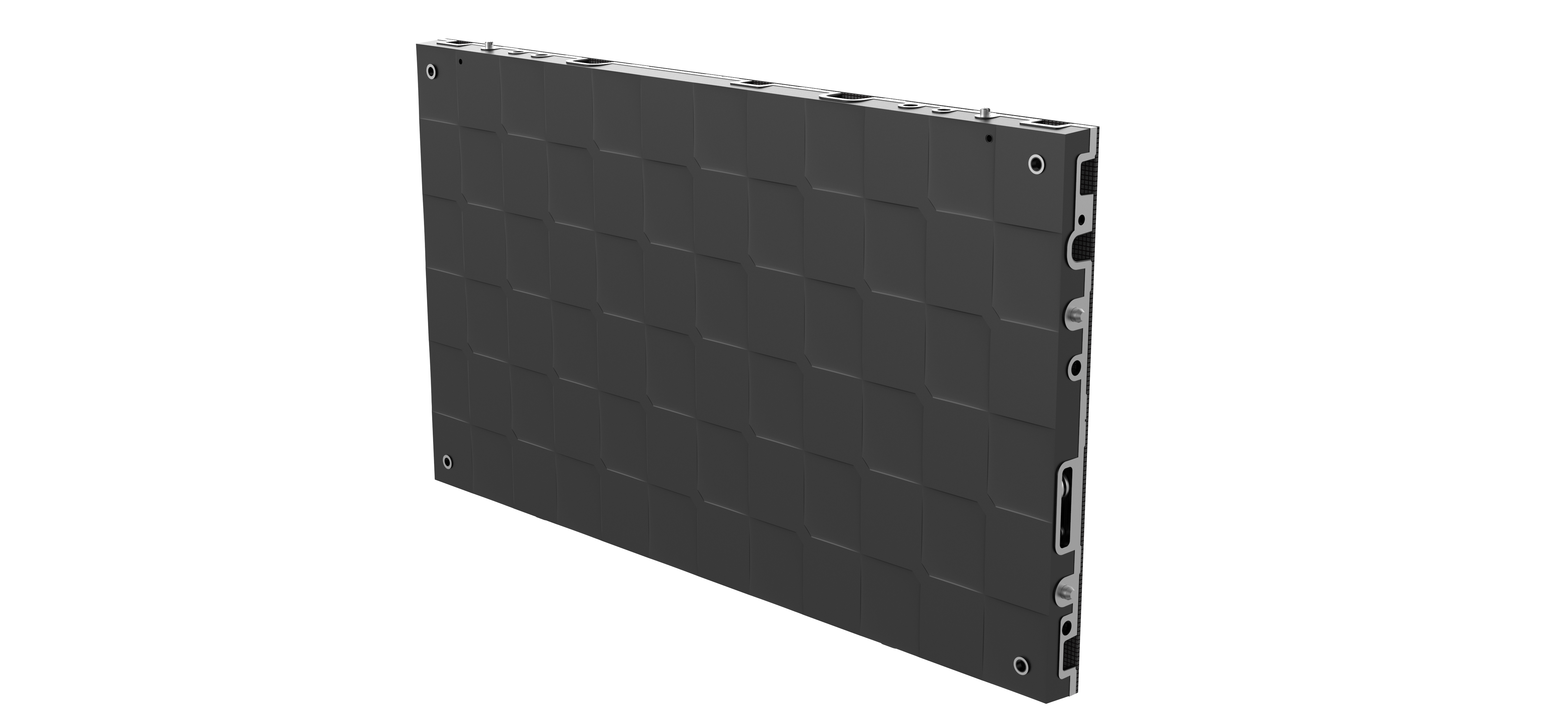
The series offers two panel formats: 600 × 337.5 × 39.5 mm and 600 × 675 × 39.5 mm, with panel weights of 4 kg and 7.9 kg. Both formats share the same 600 mm width and the same 39.5 mm depth, and both are built on the same 150 × 168.75 mm module. The geometry is worth reading carefully, because it drives the wall layout:
- 600 × 337.5 mm is an exact 16:9 panel. It is the natural building block where the wall has to carry native 16:9 sources, multi-window layouts or standard camera tiles.
- 600 × 675 mm is the same width at double the height — equivalent to two stacked 16:9 units. It reduces the number of horizontal seams on tall walls and suits walls that are closer to square, or where vertical content such as process diagrams, site plans or camera stacks dominates.
- Both heights divide cleanly on the module grid. The 150 mm module width divides the 600 mm panel width four times; the 168.75 mm module height divides the 337.5 mm panel height twice and the 675 mm panel height four times. Because the module is shared across formats, spares and service procedures are common to the whole series.
- At 39.5 mm deep, the panel is slim enough to mount flush without a rear service cavity — a direct consequence of the front-service design described below.
Flip Chip COB technology and the matt surface
ECOB Series panels use Flip Chip COB technology, which contributes to enhanced reliability, and COB integrated packaging improves protection of the LEDs against impact, dust and environmental factors. That protection matters in rooms where the wall runs continuously and where access to the screen is difficult. The matt COB surface treatment is specified for control room and command centre environments, where a glossy surface would reflect room lighting, desk lamps and operator screens back into the image.
The optical specification supports that duty. Contrast ratio is 10,000:1 and the viewing angle is 160°, so camera tiles at one end of the wall and trend charts at the other remain legible to operators sitting off-centre — in an operations room, viewing angle is a legibility requirement, not a comfort feature. Refresh rate is specified at 3840 Hz, which is relevant wherever the wall appears in a camera shot, in a recording, or in a feed that is re-broadcast.
Brightness, contrast and power design
Brightness is 600 nits as standard, with a 1000-nit option. Because control rooms are dim by design, the standard 600-nit configuration is normally the correct starting point: the display can be driven at reduced brightness while retaining grayscale depth, which is the behaviour described in indoor operations scenarios as low brightness with high grayscale. The 1000-nit option is specified where ambient light is higher than a typical control room — glazed operations centres, showroom-facing command walls, or rooms where the screen must stay legible in daytime with the lights on.
Power design is a specification choice rather than an internal detail. The ECOB Series accepts AC 100–240 V input, so one product configuration can be deployed into 110 V and 220–230 V markets without a different power platform. The series is offered in both common-cathode and common-anode designs. In a common-cathode design the red, green and blue dies are driven over separate cathode paths, which is generally associated with lower power consumption and lower heat generation than common-anode driving; common-anode follows the more traditional shared-anode arrangement. Whichever design is quoted should be recorded on the specification sheet, because it affects the power budget, the heat load and the running cost of a wall that operates continuously.
Lifetime and operating environment
Rated lifetime is 100,000 hours at 50% brightness. On a continuously operated wall, that figure is a statement about the LED package and the thermal design rather than about the calendar, which is why the environmental specification belongs in the same paragraph. The operating range is −10 °C to +40 °C, and the product is intended for indoor fixed installation. Efficient heat dissipation and stable long-term operation are part of the indoor requirement set this class of display is designed against: in practice the cabinet acts as the thermal path, and the front-service route allows a failing module or power component to be replaced without shutting down the rest of the wall.
Service access: front maintenance in a room that cannot close
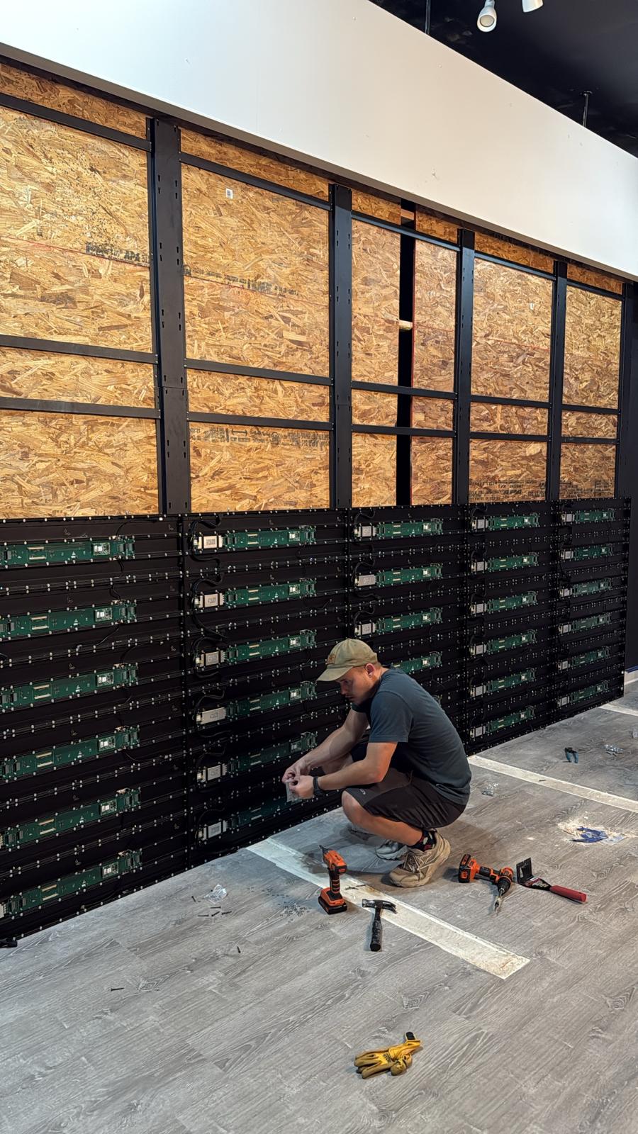
ECOB Series panels are front-service, so modules and internal components are reached from the display face. The wall therefore does not need a rear service corridor, a removable ceiling hatch above the screen, or a shutdown plan to reach the back of the cabinets. In a room that runs 24/7, that is the difference between a service window arranged in minutes and a maintenance event that takes the room out of service. Front service is also what makes direct mounting onto a structural wall or a shallow frame practical at 39.5 mm panel depth.
| ECOB Series specification | Value |
|---|---|
| Pixel pitch options | P0.625, P0.78, P0.93, P1.25, P1.56, P1.87 |
| Panel formats | 600 × 337.5 × 39.5 mm and 600 × 675 × 39.5 mm |
| Panel weight | 4 kg and 7.9 kg |
| Module size | 150 × 168.75 mm |
| LED technology | Flip Chip COB, COB integrated packaging, matt COB surface treatment |
| Cabinet material | Die-cast aluminium cabinet |
| Maintenance | Front-service maintenance |
| Brightness | 600 nits standard, 1000 nits optional |
| Contrast ratio | 10,000:1 |
| Refresh rate | 3840 Hz |
| Viewing angle | 160° |
| Operating temperature | −10 °C to +40 °C |
| Input voltage | AC 100–240 V |
| Power design options | Common cathode and common anode |
| Rated lifetime | 100,000 hours at 50% brightness |
Step-by-Step Breakdown: From Room Survey to Shipped Cabinets
- Step 1 — Survey the room, not the product. Record the closest operator position, the seating layout and sight lines, the content that must be readable, the ambient light level, the wall aperture, the structure behind it and the available power. The indoor scenario assumption is close viewing distance, controlled lighting, limited installation space and continuous operation; if any of those does not hold for the room, the specification has to change before a pitch is chosen.
- Step 2 — Set the pixel pitch from the closest position. Begin at the coarse end of the P0.625–P1.87 range and step finer only until the closest-viewing requirement is met, testing against the smallest content element.
- Step 3 — Lay out the wall on the panel grid. Work in 600 mm horizontal increments and choose between 337.5 mm and 675 mm panel heights. Decide where native 16:9 windows sit and check that they land on panel boundaries; the 600 × 337.5 mm panel is an exact 16:9 unit, so those windows can be planned without compromise.
- Step 4 — Fix brightness and power design. 600 nits standard for a dim room, 1000 nits optional where ambient light is higher; common cathode or common anode; AC 100–240 V input for one power platform across markets.
- Step 5 — Confirm the control chain. A control room wall is one element of a chain that typically includes a sending box, receiving cards, a video processor, a media player or control computer, video conferencing equipment, audio and a content management system. Each source has its own resolution and aspect behaviour, so the layout from Step 3 should be re-checked against them.
- Step 6 — Confirm service access, structure and spares. Front service removes the rear access requirement; agree the spare list — modules, power supplies, receiving cards — at the same time as the order rather than after the first failure.
- Step 7 — Confirm compliance for the destination market. DDW holds a CE-EMC Certificate of Conformity (certificate number BKC25062531FC, issued by Shenzhen BKC Testing Co., Ltd. on 2025-07-01, valid to 2030-07-01, covering EN 55032:2015+A11:2020+A1:2020, EN IEC 61000-3-2:2019+A1:2021+A2:2024, EN 61000-3-3:2013+A1:2019+A2:2021 and EN 55035:2017+A11:2020); a CE-LVD certificate of conformity (HXTS2506230030001-1, issued by Shenzhen Huaxintong Testing Technology Service Co., Ltd. on 2025-06-27, valid to 2030-06-27, against EN IEC 62368-1:2020+A11:2020 under Directive 2014/35/EU); an EU RoHS 2.0 certificate of conformity (HXTS2506230030007-1, issued 2025-06-27, against Directive 2011/65/EU as amended by EU 2015/863/EU); an FCC Supplier’s Declaration of Conformity (BKC25062532FC-R1, against FCC Part 15 Subpart B and ANSI C63.4:2014) for the US market; and an ISO 9001:2015 quality management certificate (12824Q21369R0S, issued by China Standards Institute (Beijing) Certification Center, valid to 2027-10-09). The DCOB Series COB display carries certifications including CCC, Energy Saving, CE, CB, FCC and ETL. Buyers should confirm which certificate set applies to their exact model, configuration and market.
- Step 8 — Validate, then produce. Quality control covers 100% product inspection, aging test, module testing, brightness and colour calibration, waterproof test, power safety test and performance inspection before shipment. Minimum order quantity is one unit or a project-based order, and standard-product lead time is 15–30 days; customised projects depend on product design, quantity and technical requirements.
Use Cases: Where This Specification Pattern Applies
Control rooms and command centres
The primary application. Operators sit close to the wall, ambient light is controlled, the display runs continuously, and the content mix combines camera tiles, schematics and tabular data. The combination of a fine pitch matched to the closest seat, a 600-nit standard brightness that can be driven down without losing grayscale, front service, and a 39.5 mm panel depth that allows flush mounting is what makes this configuration suitable for rooms where wall space behind the screen does not exist.
24/7 operations and monitoring rooms
Where the wall is expected to run day and night, two specification points carry the project: the common-cathode option for a lower power and heat load, and the 100,000-hour rating at 50% brightness. Service access is the third: with front service, a module or power component can be replaced from the room side without closing the operations floor.
Rooms where the wall appears on camera
Broadcast-adjacent and recorded environments place two extra demands on the display: a matt COB surface that does not reflect studio lighting back at the camera, and a 3840 Hz refresh rate, which is generally specified wherever the screen is captured on camera.
Conference, meeting and showroom walls with close viewing positions
The same selection logic — pitch from the closest seat, panel height from the wall and content layout, front service from the room — applies to fixed indoor walls in meeting spaces and showrooms where viewers are close to the screen. Where a room needs an integrated display with its own control electronics and audio rather than a wall built from panels, an all-in-one approach is usually the more practical route.
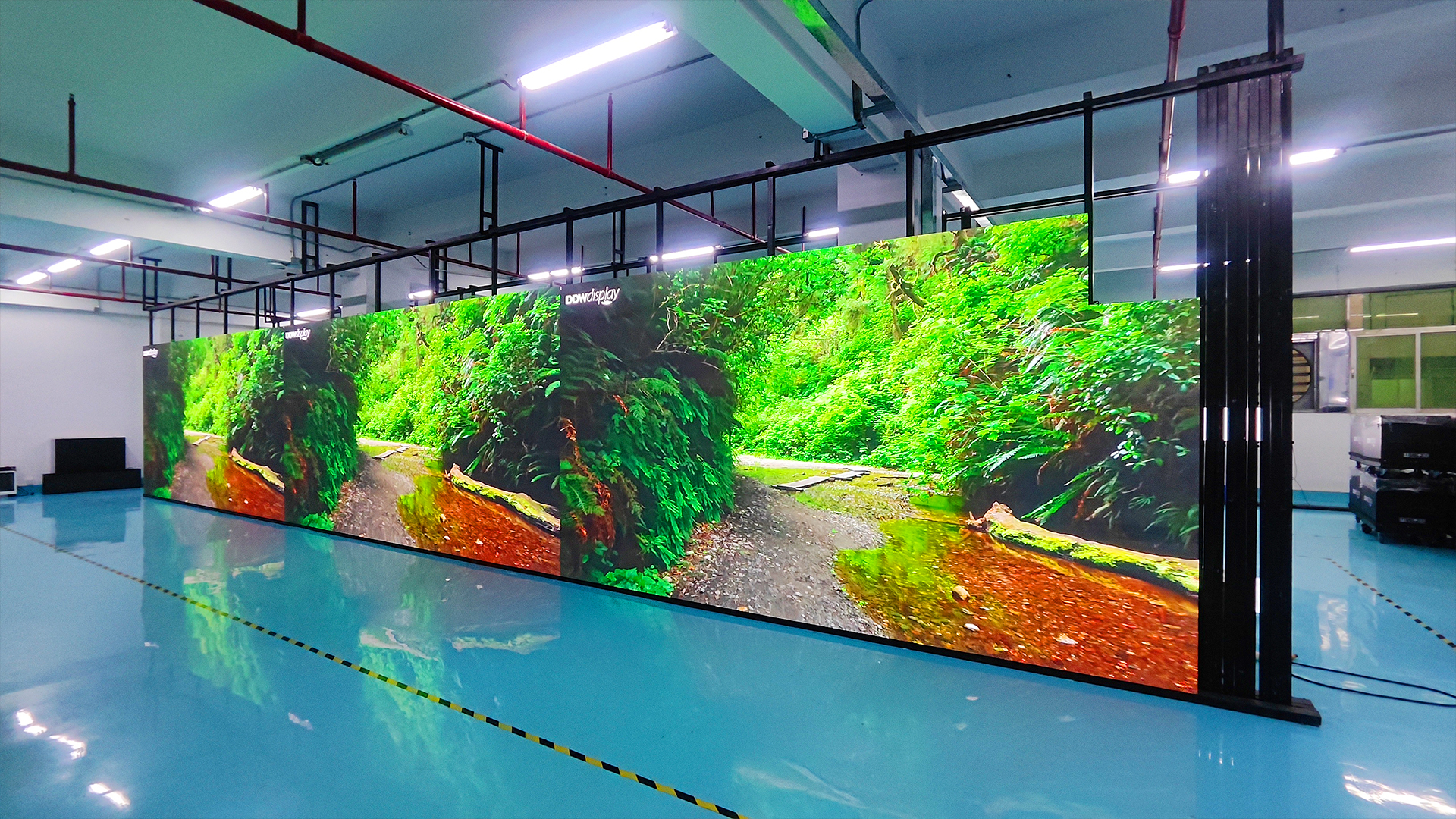
Delivery evidence from the same manufacturing base supports this class of indoor fixed work. DDW has delivered a 30² FU Series P2.604 indoor LED display for a cinema in Albania with wall-mounted installation, fine-pitch LED technology and seamless visual performance, and a 5 × 3 m, 15² FU Series P1.95 GOB indoor LED display for a shopping mall in the United States. Both projects are indoor fixed fine-pitch installations, which is the same installation discipline required by a control room wall — a fixed structure, front access, and continuous daily operation.
Comparison Table: Indoor Fine-Pitch Options in the DDW Portfolio
The table below compares the indoor fixed fine-pitch options using published product specifications. It is intended to show where each option fits, not to rank them: the correct choice is the one that matches the viewing position, the wall geometry and the service route of the specific room.
| Option | Pixel pitch | Cabinet / panel | Maintenance | Notable specification points | Typical indoor fit |
|---|---|---|---|---|---|
| ECOB Series (Flip Chip COB) | P0.625, P0.78, P0.93, P1.25, P1.56, P1.87 | 600 × 337.5 × 39.5 mm and 600 × 675 × 39.5 mm; 4 kg / 7.9 kg; module 150 × 168.75 mm; die-cast aluminium | Front service | 600 nits standard / 1000 nits optional; 10,000:1 contrast; 3840 Hz; 160°; −10 °C to +40 °C; AC 100–240 V; common cathode and common anode; matt COB surface; 100,000 hours at 50% brightness | Control rooms, command centres, close-viewing fixed walls |
| QDCOB Series (Quantum Dot COB) | P0.78, P0.9375, P1.25, P1.5625 | Aluminium cabinet; COB integrated packaging | Front maintenance | Quantum Dot COB technology; high contrast; high gray scale; wide viewing angle | Conference rooms, control rooms, command centres, broadcast studios |
| HK Series (SMD / GOB / COB options) | P1.25, P1.53, P1.86, P2, P2.5 | 640 × 480 mm cabinet, 6.5 kg; cabinet flatness ≤0.1 mm; aluminium profile | Full front access | 300–600 cd/m² adjustable; up to 8,000:1 contrast; ≥3840 Hz; 160°/160°; 14–16 bit; IP45; AC 110–240 V | Conference rooms, control rooms, commercial indoor spaces |
| FU Series (fine pitch indoor) | P1.56, P1.95, P2.5, P2.6, P2.9, P3.91 | Cabinet options 1000 × 250 mm / 750 × 250 mm / 500 × 250 mm; 6.4 kg for 1000 × 250 mm; module 250 × 250 mm | Front maintenance | 800–1000 nits (P1.56–P2.9), 1000–1200 nits (P3.91); 7680 Hz; 14 bit; IP31; 90° right-angle splicing | Conference rooms, showrooms, control rooms, retail indoor walls |
FAQ: Indoor Fine-Pitch COB LED Display Specification
Which certificates should I confirm before ordering an indoor COB LED display for the EU or the US?
Certification is market-specific and should be matched to the exact model and configuration. For the EU/EEA market, DDW holds a CE-EMC Certificate of Conformity (certificate number BKC25062531FC, issued by Shenzhen BKC Testing Co., Ltd. on 2025-07-01, valid to 2030-07-01, covering EN 55032:2015+A11:2020+A1:2020, EN IEC 61000-3-2:2019+A1:2021+A2:2024, EN 61000-3-3:2013+A1:2019+A2:2021 and EN 55035:2017+A11:2020), a CE-LVD certificate of conformity (HXTS2506230030001-1, against EN IEC 62368-1:2020+A11:2020 under Directive 2014/35/EU) and an EU RoHS 2.0 certificate of conformity (HXTS2506230030007-1, against Directive 2011/65/EU as amended by EU 2015/863/EU). For the US market, an FCC Supplier’s Declaration of Conformity is held under BKC25062532FC-R1, against FCC Part 15 Subpart B and ANSI C63.4:2014. Quality management is certified to ISO 9001:2015 (certificate 12824Q21369R0S, issued by China Standards Institute (Beijing) Certification Center, valid to 2027-10-09). The DCOB Series COB display additionally carries certifications including CCC, Energy Saving, CE, CB, FCC and ETL. Before the order, ask the manufacturer which certificate applies to your model, configuration and destination market, and request the certificates or test reports themselves rather than a summary.
How do I decide between P0.625, P0.93 and P1.87 for a control room wall?
Start from the closest operator position and the smallest content element that must be read, then choose the largest pitch that still satisfies both. P1.87 and P1.56 suit rooms where the nearest seat is further from the wall and the content is graphic or chart-based. P1.25 is a common middle step where data tables and camera tiles must stay readable near the front row. P0.93, P0.78 and P0.625 belong to rooms with genuinely short viewing positions or to walls used as high-density visualisation surfaces. Moving finer increases LED density per unit area and the material content of the display, so a pitch chosen one or two steps finer than the room requires usually adds cost without adding readable information. The ECOB Series covers all six steps — P0.625, P0.78, P0.93, P1.25, P1.56 and P1.87 — so the decision can be made on the room rather than on availability.
What drives the cost of an indoor fine-pitch COB LED wall?
Four variables dominate. The first is pixel pitch: a finer pitch raises the number of LEDs per unit area. The second is brightness configuration — the ECOB Series is specified at 600 nits standard with a 1000-nit option, and the higher option changes the power and thermal design. The third is power architecture: common-cathode and common-anode designs are both offered, and the choice affects power consumption, heat load and the running cost of a wall that operates continuously. The fourth is the physical build — panel count driven by wall size and the choice between the 600 × 337.5 × 39.5 mm and 600 × 675 × 39.5 mm formats, plus the structure, control chain, installation and spare parts. Front-service maintenance reduces the access cost of the project, because no rear service corridor has to be built or maintained. A realistic comparison should therefore be made on the configured wall, not on a price per square metre for the panel alone.
Can we validate a sample or a pilot panel before committing to a full order?
Yes. Minimum order quantity for DDW LED display products is one unit or a project-based order, so a single panel or a small pilot wall can be produced and evaluated before the full quantity is released. Customisation covers pixel pitch, LED module size, cabinet size, cabinet structure, display shape, brightness level, refresh rate, installation method, control system, logo branding, colour calibration, power solution and mechanical design. Every unit goes through 100% product inspection, aging test, module testing, brightness and colour calibration, power safety test and performance inspection before shipment, and the resulting records can be used as the validation evidence for the pilot build. Validating one panel of the specified pitch, brightness and cabinet format is the most reliable way to confirm that the closest viewing position and the wall layout behave as expected.
What is the lead time, and what support is available after delivery?
Lead time is 15–30 days for standard products; customised projects depend on product design, quantity and technical requirements, so the schedule should be confirmed against the final configuration. After delivery, DDW provides remote technical support, installation guidance, troubleshooting support, product warranty service, spare parts supply and professional engineering assistance. Because ECOB Series panels are front-service from the display face, module, power and receiving-card replacements can be carried out from the room side without dismantling the wall. To start a control room specification, send the room dimensions, the closest viewing position, the content types and the destination market to info@ddw.net, or contact the team on WhatsApp at +86 134 1755 8100.
Conclusion: Specify the Room Before the Panel
For an indoor fine-pitch COB LED display in a control room, the specification resolves into three decisions that must be taken in sequence. Pixel pitch comes first, and it is set by the closest operator position and the smallest content element that has to be read — not by the finest number available. Panel geometry comes second: the ECOB Series gives one 600 mm grid with two panel heights, so a wall can be planned on an exact 16:9 unit at 600 × 337.5 × 39.5 mm or on the double-height 600 × 675 × 39.5 mm format, both sharing the same 150 × 168.75 mm module. Service access comes third, and front-service maintenance removes the rear service corridor that most operations rooms cannot provide.
Around those three decisions sit the supporting specifications that define continuous indoor operation: Flip Chip COB packaging with a matt surface treatment, 600 nits standard or 1000 nits optional brightness, a 10,000:1 contrast ratio, 3840 Hz refresh, a 160° viewing angle, −10 °C to +40 °C operating range, AC 100–240 V input, a choice of common-cathode or common-anode power design, and a rated lifetime of 100,000 hours at 50% brightness. Confirm the destination-market certificates at the same time, and validate one panel before releasing the full quantity. A wall specified in that order stands a far better chance of being the wall the room actually needed.
Next step: put the room on paper first
Send the wall dimensions, the closest viewing position, the content types and the destination market to DDW Display. You will receive a configuration proposal built on the ECOB Series pixel pitch and panel format that match the room, together with the relevant certificate pack.
Email: info@ddw.net | WhatsApp / WeChat / Mobile: +86 134 1755 8100 | Website: www.ddw.net
Download the full product range: DDW LED Display catalog 2026 (PDF)
Factory address: 2F Building 8, YiLisheng Industry Park, Fuyong, Baoan, Shenzhen, 518103, China

Have Questions or Need More Details?
Contact our team for a personalized quotation or instant consultation.
Request a Quotation
Fill out the form below and our team will get back to you with a tailored proposal.
WhatsApp Direct Chat
Prefer to chat in real-time? Message us on WhatsApp for instant assistance & quick answers.
- Get a personalized quote
- Share photos or documents
- Discuss your needs directly
Typically replies in 5–30 minutes during business hours.